

We built the
bench that
proves a drive
is ready for the
road.
A high-voltage test system for electric bus and truck driveline components.
HV DRIVELINE TEST BENCH · BUILT 2021–2022 · ANJOU QC / COMING TO THE US SOON
One bench, the full qualification sequence
The bench takes a driveline component from bare motor to signed-off report — static electrical checks, dynamic run-in, and pass/fail documentation — without moving it between rigs.
STATIC
Electrical qualification
Winding and sensor resistance, insulation resistance, surge, and AC withstand — the checks that catch a manufacturing or repair defect before power is ever applied.SAFETY
Category 4 interlocks
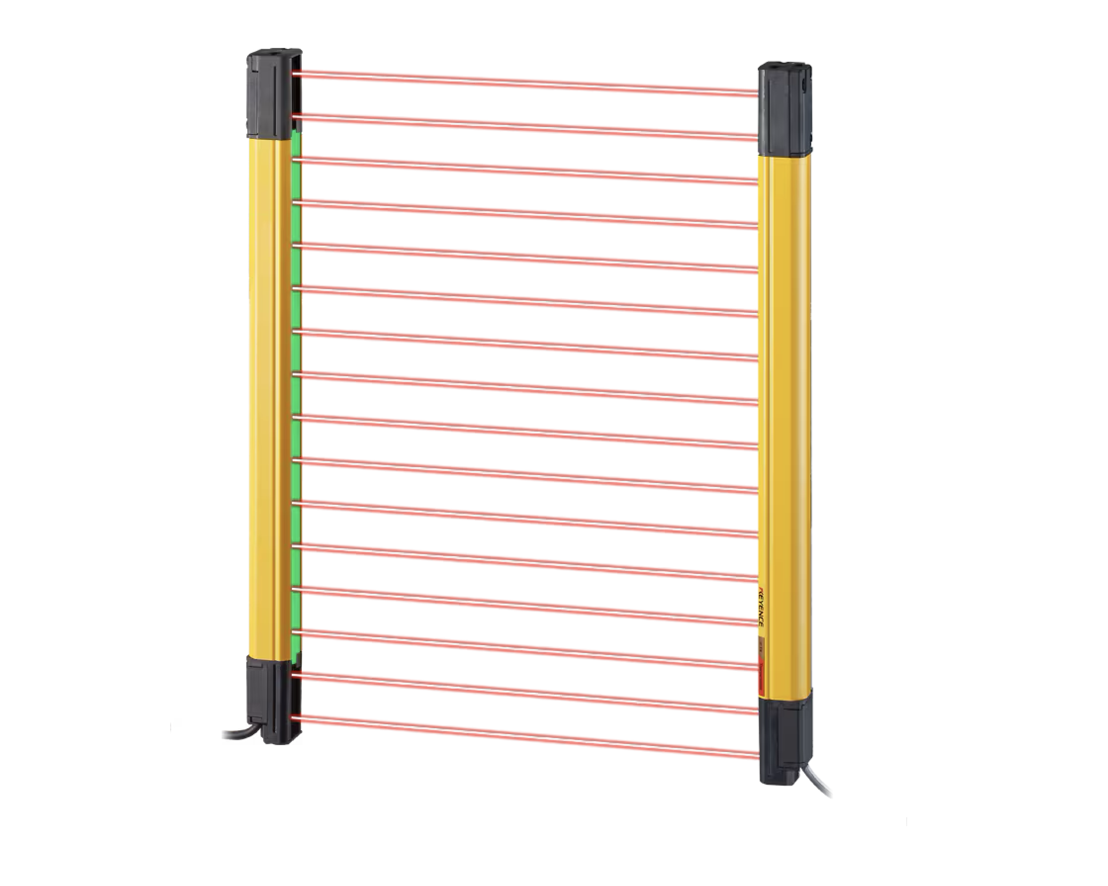
Laser safety curtains and an emergency-stop circuit rated PL e / SIL 3 guard every energized test.DYNAMIC
Run-in & load
Frequency-converter-controlled speed ramps to full operating RPM, with continuous bearing temperature and vibration monitoring.DATA
Wireless, logged, shareable
Results are captured wirelessly and stored for long-term reliability research — the same data pipeline that feeds Gotham's predictive-maintenance models.REPORTING
Automated pass / fail
Every measurement is logged against its specification automatically — no manual transcription, no paper travelers.MODULAR
Motor or full axle
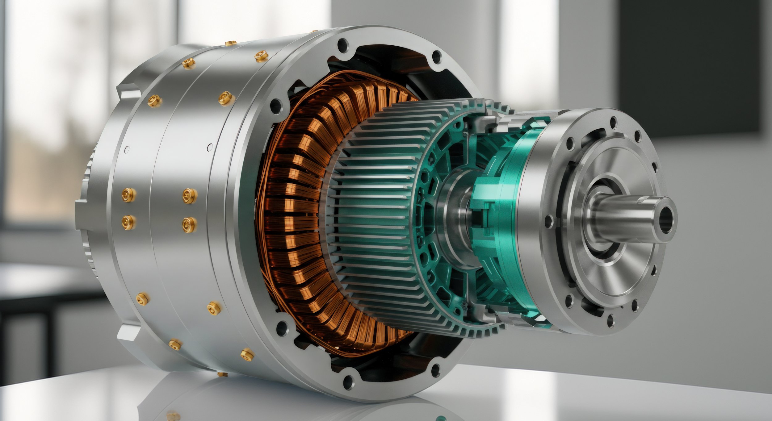
Fixtures swap between a single e-motor and a complete driven axle, across asynchronous and permanent-magnet designs.
Our testbench was designed to be modular and adaptive to all types of electric and hydrogen systems.
Contact our engineers to build your own custom testing sequence based with your own testing requirements.
The sequence, in order
Every component runs the same seven-step sequence — static checks first, then load.
01 Cold resistance — winding & temperature sensors
A four-wire DC measurement (200 mA) removes lead-wire resistance from the reading, so the winding and each embedded sensor (KTY, PT1000, or NTC
depending on platform) can be checked against its manufacturer tolerance curve at ambient temperature.
METHOD
4-wire DC, 200 mA
02 Insulation resistance — DC Hipot
A DC test voltage — always set above the platform's maximum operating voltage — is applied winding-to-housing to confirm no hazardous touch current can occur, per ECE-R100 and ISO 6469-3.
TEST VOLTAGE
1.0 kV DC
DWELL TIME
60s
MIN. RESISTANCE
> 400 MΩ*
Pass: measured resistance exceeds the platform threshold (up to > 1.99 GΩ dry) with leakage current under 2.5 µA. *Threshold varies by platform.
03 Surge test — Baker comparison
A fast voltage impulse is injected into each winding and the resulting decaying waveform is compared phase-to-phase. A weak turn, coil, or phase-to-phase insulation defect shows up as a waveform that separates from the others.
REFERENCE STANDARD
IEC 60034-18-41
05 AC withstand voltage — sensors
The same withstand check is repeated for the embedded temperature sensor circuit, both against the housing and against the winding, since the sensor leads run alongside the HV conductors.
07 Run-in & dynamic tests
A variable-frequency drive ramps the motor through a defined multi-stage speed profile up to full rated RPM to run in the bearings, while bearing temperature and housing vibration are recorded continuously. Newer platforms add induced-voltage and short-circuit-current checks at a fixed shaft speed.
RAMP RATE
10 Hz/s (±1 Hz/s)
SYMMETRY LIMIT
≤ 3% phase-to-phase
LEAKAGE LIMIT
~1 mA (max 4 mA)
REFERENCE
Manufacturer curve
Pass: all three phase measurements fall inside the temperature-adjusted range, with under 3% deviation between phases.
Pass: phase-to-phase EAR% stays below roughly 3–7% depending on platform, with no visible waveform separation.
TYPICAL VOLTAGE
1,000–1,200 Vrms
DWELL TIME
Error Area Ratio (EAR%)
PULSE CAPACITANCE
100 nF (standard)
04 AC withstand voltage — winding to housing
The complete insulation system — material, clearance, and creepage distance — is checked against the housing/frame at a voltage derived from IEC 60349-2:1000 V + 2 × the platform's DC bus voltage, held for 60 seconds.
FORMULA
1000V + 2×UDC
TEST DURATION
60s
LEAKAGE LIMIT
~10 mA (max 20 mA)
Pass: leakage current stays within the supplier-set limit and no flashover occurs during the full dwell.
Pass: leakage current stays within the supplier-set limit and no flashover occurs during the full dwell.
06 Air pressure / leak test
For axle assemblies, a sealing fixture is mounted on the hub carrier and the housing is pressurized through the fill plug, then inspected for leaks at every seal and the bearing cover.
STARTING PRESSURE
0.5 bar
MAX PRESSURE
2 bar
INSPECTION
Leak-detection spray
Pass: no bubbling or pressure drop observed at any seal or the B-bearing cover.
VIBRATION LIMIT
< 1.5 mm/s
DRIVE CONTROL
Danfoss VLT FC 302
Pass: vibration velocity stays under 1.5 mm/s throughout the run, with bearing temperature within the expected rise curve.
What's actually on the bench
The core test and measurement equipment, most of it automated and PLC-controllable for unattended sequencing.
Instrumentation
-
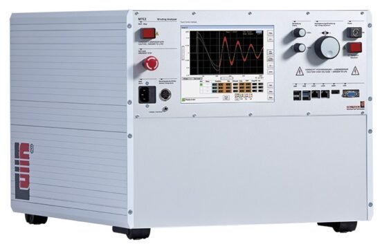
Automated Hipot, AC withstand, and Baker surge tester with PLC remote-control interface.
-
4-wire resistance and insulation-resistance meter for winding and sensor checks.
-
Variable-frequency drive controlling run-in speed ramps and dynamic tests.
-
Housing vibration monitoring during bearing run-in.
-
Dual-channel Hall sensor for shaft speed and rotation direction.
-
Winding and bearing temperature sensing across all three platforms.
-
Platform-specific connectors bridging the motor harness to test leads.
-
Electric powertrain safety requirements for vehicle approval.
-
Rating and performance of rotating electrical machines.
-
Partial-discharge-free insulation qualification and QC testing.
-
Field evaluation of electrical equipment — mandatory in the US & Canada.
-
Protection of persons against electric shock hazards.
-
Converter-fed AC traction motors — rail and road vehicles..
-
Impulse-voltage test methods for insulating materials.
Standards the sequence is built on
Every test traces back to a named clause, not an internal rule of thumb.
Category 4 Safety Interlocks
Every energized test runs behind a PL e / SIL 3 laser safety curtain (30 mm detection resolution) and an emergency-stop circuit, with a defined 1.53 m approach boundary during hi-pot testing and ESD protocol for anyone handling sensor leads.

Built 2021–2022 as a joint research project between Polytechnique Montréal and ZF service partner Solutions Serafin — the same driveline-testing discipline now feeding Gotham Quantum Energy's predictive-maintenance and battery-intelligence platform.